Amorphous Metal Transformers – Myth Buster
What are Amorphous Core Transformers (AMT’s)?
The cores of conventional transformers consist of stacks of laminations that are made from silicon steel with an almost uniform crystalline structure (CRGO). In transformers with amorphous cores, a ribbon of steel is wound to form the core. The big benefit of amorphous transformers is that amorphous steel has lower hysteresis losses. Simply put this means that less energy is wasted as heat during magnetisation and de-magnetisation of the core (see IR imagery below).
What are Amorphous Metals?
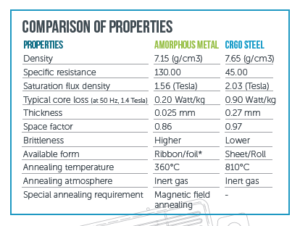
Amorphous metals are made of alloys that have no atomic order. They are made by rapid cooling of molten metals that prevents crystallisation and leaves a vitrified structure in the form of thin strips. Due to the lack of systematic structure, this type of metal has also been given the name “The Metallic Glasses”.
Bolted Short Circuit Constraints using Amorphous Core Material
MYTH: A transformers qualification is conditional on the devices ability to withstand electrodynamic stresses during bolted short circuit tests (IEC 60076 Part 5).
This constitutes the major limitation of using Amorphous Core Transformers – and has limited the use of these types of transformers to low outputs and single phase devices below 250kVA.
TRUTH: To evaluate the short circuit withstand capacity of amorphous metal transformers, we have conducted a short circuit test on a 35/0.4kV transformer. It has passed the SC test successfully and the design is established and validated. For transformers of ratings above 250kVA we use foil for the LV windings. Usage of foil reduces axial forces and increases the short circuit withstand capacity of transformers. Radial forces are supported on the sides of the coil by a core pressing frame arrangement and solid phase to phase and phase to core insulation. We use epoxy diamond dotted (EDD) paper as inter layer insulation for LV & HV windings. EDD paper is made by applying heat curable resin in the form of square shaped dots on both sides of the kraft paper. The pattern of the resin dots ensures that there is sufficient space between them for oil impregnation. Windings made by this process are dried in the oven during which resin melts and cures. Through this process the layers are glued together and the complete winding becomes a solid block. The short circuit strength of such windings is considerably higher than that of conventional systems.
Limitation in the Magnetic circuit design using Amorphous Core Material
MYTH: Magnetic circuit comprises of single phase pre assembled rolled sheet elements, annealed at approx 350 Deg C – this dictates rectangular section design with all associated constraints in winding & short circuit stress resistance.
TRUTH: The construction of amorphous core dictates windings of rectangular construction . Once a design has been established, rectangular windings can be easily made. Rectangular windings also withstand short circuit forces by using foil and radial clamping arrangements as highlighted above.
Material Width Availability Constraint
MYTH: In silicon steel technology, the mother rolls are approx 1000mm wide and can be used to produce many varieties of widths of steel to optimise magnetic circuit designs and create designs to meet many varying customer standards. Amorphous steel sheets are currently only available in 3 widths which restricts design optimisation. Additionally, the number of world wide suppliers of Amorphous steel is extremely limited making the material price extremely volatile and unpredictable.
TRUTH: Even though the availability of amorphous material is limited to only three widths (142.2mm, 170.2mm and 213.4mm), by varying the number of core stacks and their thickness we can achive optimum transformer design. Since patent expiry of amorphous steel production there have beena number of additional suppliers and raw material prices are stable.
Intrinsic Fragility of Amorphous Material
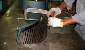
MYTH: Material fragility is both the most immediate and most problematic constraint in the use of Amorphous core material. The material itself was initially known as “metallic glass”. The fragility of amorphous sheet is equivalent to that of glass and like glass it bursts into tiny fragments once pushed beyond its bending limit. Sheet splinters are unavoidably produced when opening and closing circuit elements during coil installation.
TRUTH: Because amorphous material is very thin (20-25microns) splinters are produced during the manufacturing process. We avoid the occurence of core splinters by applying the process below:
A. Epoxy coating is applied on both sides of assembled core except at coil openning position. Thus individual core laminations become a solid block and will remain in position. In addition to this the core assembly is wrapped with CRGO sheets to provide mechanical strength.
B. To reduce the effect of forces on core assembly during transformer operation, FRP insulation is provided between LV and core. Forces generated during transformer operation are absorbed by FRP thereby reducing force on core.
Low Resistance to External Stresses using Amorphous Core Material
MYTH: In silicone steel technology, once the magnetic circuit has been installed it is rigid and acts as mechanical support on which all the transformer elements rest. In amorphous technology, the circuit elements are closed at the bottom end – this is a fragile area which must not be submitted to any stress. The weight of the device, in particular is to be avoided. Additionally, as the transformers are manufactured in India the transportation stresses could effect the integrity and reliability of the transformers used within the UK.
TRUTH: In amorphous core transformers, core is supported by the winding assembly and core clamps. To arrest movement of core coil assembly during transit, CCA is locked to the tank with a bolting arrangement.
Specific Constraints on the Windings
MYTH: The rectangular section of the magnetic circuit calls for the windings to be of the same type – but rectangular windings offer poor resistance to bolted short circuit stresses. Additionally in conventional technology, the magnetic circuit carries the coils and they are locked onto it. In amorphous technology, it is the magnetic circuit that rests on the windings and their base.
TRUTH: For transformers of ratings above 250kVA we use foil for the LV windings. This reduces axial forces and increases the short circuit withstand capacity of the transformer. Radial forces are supported on the sides of the coil by core pressing frame arrangement and solid phase to phase and phase to core insulation. We use epoxy diamond dotted (EDD) paper as inter layer insulation for LV & HV windings. EDD paper is made by applying heat curable resin in the form of square shaped dots on both sides of the kraft paper. The pattern of the resin dots ensures that there is sufficient space between them for oil impregnation. Windings made by this process are dried in the oven during which resin melts and cures. Through this process the layers are glued together and complete winding becomes a solid block. The short circuit strength of such winding becomes considerably increased compared to conventional systems.
Manufacturing Constraints using Amorphous Core Material
MYTH: Avoidance of sheet splinters polluting the transformer and the manufacturing area is virtually impossible. There is a requirement for constant and suitable cleaning of the assembly areas. As amorphous steel is only 20-25 microns thick, the splinters tend to stick together easily as they are very light and smooth. Removal of the splinters is difficult and as such could contaminate the dielectric fluid and ingress into the actual windings due to fluid flow and cause failures to the windings.
TRUTH: In amorphous core transformers, the possibility of splinters exists at the core overlapping area. During the manufacturing process, the core overlapping area is put at the bottom and a chip containment arrangement is provided for the core. Thus any core splinters that had formed will get collected in the chip containment arrangement and do not float in oil.
Noise
MYTH: Amorphous sheet is noticeably noisier for the same induction than silicon sheet – and may become louder over time due to the magnetostrichen of the core plates and the effects of material splinters.
TRUTH: When compared to CRGO transformers noise levels in amorphous metal transformers are higher due to the larger volume of core material. Noise levels as per ENATS can be met with amorphous.
Constant Loss for the No Load Loss using Amorphous Core Material
MYTH: Due to the limited use of amorphous core materials, it is not known if the characteristic of the material remain constant during the life expectancy of the transformer ( expected life 25 years) – unlike known facts regarding traditional silicon steel.
TRUTH: Amorphous transformers exhibit constant no load losses over their lifetime. This has been demonstrated by conducting losses measurements test on transformers that are already in service. One such measurement has been carried out on 63kVA, 100kVA and 160kVA transformers that have been in service for 10 years. Results of the study are attached for your reference.
Why hasn’t amorphous steel been used previously?
MYTH: Amorphous Core Material has been in existence for more then 30 years but not considered by European manufactures due to the associated limitations of the material.
TRUTH: Previously the awareness of Global warming & Green house gas emissions was not as prominent as it is today and the concept of Energy efficiency was not a priority in transformer design. Amorphous core transformers are an alternative to the conventional CRGO transformers and are mainly used for the purpose of reduction of No-load losses when compared to CRGO core transformers which in turn saves significant amounts of energy.
 14 Aug 2018
IETF: Industrial Energy Transformation Fund – Phase 3
Industrial emissions account for around 18% of UK emissions. To reach the Net Zero target in 2050, industrial emissions need to fall by around 90% from today’s levels. Industrial Energy Transformation Fund (IETF) launched Phase 3 of industrial grants on Monday 29 January 2024, with the closing date on Friday 19 April 2024, and aims […]
23 Feb 2024
Guide to Replacing Transformers
The third part of the Intergovernmental Panel on Climate Change (IPCC) Sixth Assessment Report (AR6) was published earlier this month. Scientists warn that limiting global warming to 1.5°C is beyond reach but restricting temperature rise to no more than 1.5C to 2C could be the range that will minimize the likelihood of reaching critical environmental […]
22 Apr 2022
IETF: Industrial Energy Transformation Fund FAQ
The Industrial Energy Transformation Fund (IETF) was designed by the UK government to encourage energy-intensive businesses to cut their carbon emissions and reduce their energy waste by switching to energy-efficient low-carbon technologies. A budget of £315 million was allocated by the government to be spent through the IETF. BEIS manages England, Wales and North Ireland’s […]
4 Apr 2022